


Fire Safety in Commercial Kitchen Grease Duct Systems: The Importance of ASTM E2336 and UL 2221 Standards

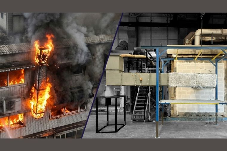
Commercial kitchens are among the most challenging areas of a building from a fire safety perspective due to high heat input, continuous ignition sources, and the constant generation of grease-laden vapors. While cooking equipment is often the point of ignition, the extent and consequences of a fire are frequently determined by developments within the kitchen exhaust system—particularly grease duct systems.
Over time, grease ducts can accumulate combustible grease deposits, creating conditions that may allow fire to propagate through the duct system. These systems often extend over long distances, passing through shafts, ceilings, and multi-story pathways. As a result, grease duct systems that are not properly designed, protected, maintained, or installed using a system-based approach may unintentionally become a pathway for the spread of fire and heat beyond the kitchen compartment.
For projects requiring fire resistance, fire-rated insulation solutions are commonly applied along grease duct routes. However, the reliability of these solutions must be validated through testing, especially for penetrations, support systems, access openings, and other critical installation details. ASTM E2336 and UL 2221 are among the most widely referenced standards used to evaluate the performance of grease duct systems under defined fire exposure scenarios.
Grease Duct Systems: A Fire Path That Can Amplify Consequences
Two major fire scenarios dominate grease duct engineering:
- Duct Internal Fire (Grease Fire): Ignition of accumulated grease deposits with flame propagation within the duct system.
- External Fire Exposure: Fire originating outside the duct, where flames from a compartment fire surround the duct route through shafts, suspended ceilings, or service spaces.
In both scenarios, the objective remains the same: maintaining compartmentation and preventing fire spread to remote parts of the building.
Because grease duct systems include elbows, joints, access panels, transitions, and penetrations, actual fire performance is not determined by a single material property but rather by the integrated performance of the complete installed system. Testing the entire assembly, including all installation components, is critical to understanding how closely field installation matches the validated configuration.
ASTM E2336 and UL 2221: System-Based Verification of Grease Duct Fire Performance
ASTM E2336 and UL 2221 serve a similar practical purpose by validating the performance of grease duct systems as complete assemblies rather than evaluating individual materials in isolation.
The assessment extends beyond insulation materials and includes:
- Joints and connections
- Support and hanger systems
- Penetration details
- Access openings
- Installation components
Both standards evaluate two primary fire scenarios:
- Internal duct fire exposure
- External fire exposure
Additionally, post-fire hose stream testing is used to challenge the integrity and durability of the system after fire exposure.
From a material perspective, non-combustibility requirements are generally based on ASTM E136, while flame spread and smoke development limitations are commonly evaluated according to ASTM E84 or UL 723.
Scope of Fire Resistance Testing
Testing is performed on insulated grease duct specimens assembled to represent real-world installations and constructed according to manufacturer installation requirements.
The tested configuration may include:
- Support systems
- Suspension elements
- Access doors
- Cleaning openings
- Penetration details
External fire testing typically simulates a duct passing through a floor assembly and extending beyond the furnace environment.
Internal Fire Exposure Conditions
During internal fire testing, gas burners raise the internal duct temperature in a controlled manner.
The test sequence generally includes:
- Increasing the internal temperature to at least 500°F (260°C) within 15 minutes and maintaining this condition for a minimum of four hours.
- Raising the temperature to at least 2000°F (1093°C) within the following 15 minutes and maintaining it for an additional 30 minutes.
Measurements and Acceptance Criteria
Temperature measurements are typically performed using:
- Four thermocouples positioned inside the duct
- At least sixteen surface thermocouples on unexposed surfaces
Critical areas monitored include:
- External surfaces
- Joints
- Support contact points
- Access door regions
Acceptance criteria generally include:
- Maximum temperature rise limits on unexposed surfaces
- No openings or structural failures
- No flame penetration to the unexposed side
- Retention of insulation integrity
- Successful post-fire hose stream performance
Critical Installation Details That Determine Field Performance
In practice, system failures frequently occur at recurring installation details:
Supports and Hangers
Improper spacing may lead to duct deflection during fire exposure, causing joint separation or penetration failures.
Joints and Connections
Insufficient fastening or incorrect components may create openings due to thermal expansion.
Access Doors and Cleaning Openings
Improperly sealed access doors can become leakage paths during fire conditions.
Wall and Floor Penetrations
Incorrect sealing methods or excessive installation gaps may create routes for fire spread.
Clearances and Separation Distances
Insufficient spacing between ducts and combustible materials can increase heat transfer and ignition risk.
These details are not secondary considerations; they frequently determine actual system performance.
Bridging Expertise and Real-World Application
Grease duct fire safety exists at the intersection of fire testing, practical design, and operational realities. The most reliable results are achieved when grease duct systems are treated as integrated systems, where tested configurations are accurately translated into field applications and installation practices remain consistent throughout the project lifecycle.
As part of its testing and validation activities, Efectis supports the assessment of technically critical project requirements and transforms these evaluations into documentation aligned with project objectives.
Source: Efectis